How to Extract Vector Schematics from PDF Datasheets into CAD
Step-by-step guide: load a component datasheet, isolate vector traces and IC footprints in Analyze mode, export clean SVG paths, and pipe geometry directly into Schema Editor.
TLDR
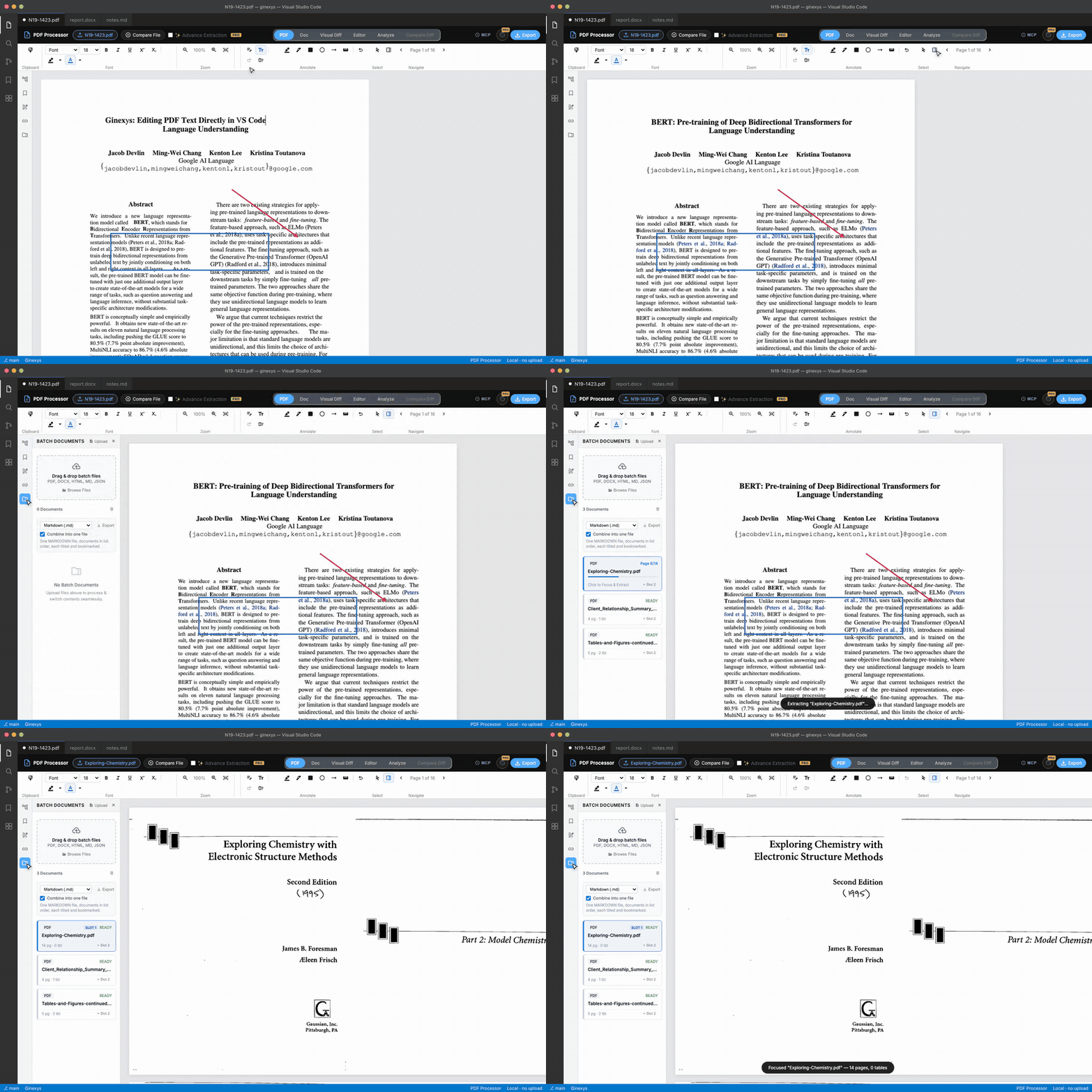
Open a hardware datasheet, navigate to the pinout or schematic page, and switch to the Analyze tab with the Vector Layer enabled. Marquee-select the IC package outline or circuit block on the canvas to isolate its clean vector lines, then click Send to Schema Editor to pipe editable vector shapes directly into your schematic canvas over local IPC.
Before you start
You need an electronic component datasheet or technical drawing PDF (such as a microcontroller pinout, PCB package dimension drawing, or reference schematic).
Vector extraction operates directly on the PDF's native drawing commands (moveto, lineto, rect), giving you razor-sharp SVG vector curves rather than pixelated screenshots.
Step 1 — Load your datasheet and navigate to the schematic page
Click Open File and load your PDF datasheet.
Use the page navigation arrows at the bottom of the window to navigate directly to the package dimension drawing or circuit diagram page (e.g. Page 12).
Step 2 — Activate the Vector Geometry layer in Analyze mode
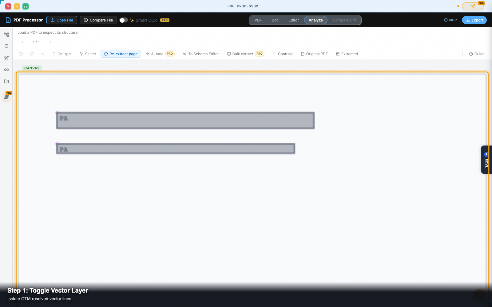
Click Analyze in the top navigation strip.
In the Analyze control toolbar, click Toggle Vector Layer:
- The canvas hides non-essential background fills and exposes the raw vector path geometry.
- Horizontal and vertical line segments highlight in bright cyan.
- Closed component rectangles (such as IC chip packages and surface-mount pads) highlight with bounding boxes.
Step 3 — Marquee-select the component package or circuit block
Click the Marquee Tool in the left-hand toolbar (or hold Shift and drag across the canvas).
Draw a selection rectangle around the exact circuit block, IC footprint, or dimensional drawing you want to extract.
The selection highlights all enclosed vector lines and pin vertices while ignoring unrelated page margins and header text.
Step 4 — Filter vector paths from raster background art
Inspect the selected elements in the right-hand Vector Properties panel:
- Isolate Lines: Filter out cosmetic fill hatching or non-conductive boundary lines.
- Normalize Scale: Choose standard millimeter (
mm) or mil units based on the datasheet's dimension scale. - Group Elements: Click Group Vector Paths to bind package pins and body outlines into a single composite symbol.
Step 5 — Send to Schema Editor or export clean SVG
Choose your export destination:
- Send to Schema Editor: Click the Send to Schema Editor button in the toolbar. This packages the vector geometry into a structured SVG envelope and opens GINEXYS Schema Editor automatically via local OS IPC, placing your new symbol directly onto the electrical canvas.
- Export SVG: Click Export > Vector SVG (.svg) to download standard vector markup for import into desktop CAD software like KiCad or Altium.
Pro tip: lossless CTM matrix scaling
When vector art is scaled inside a PDF using transformation matrices, traditional raster screenshot tools introduce blur and anti-aliasing artifacts.
PDF Processor extracts the original Current Transformation Matrix (CTM) values directly from the PDF stream, resolving exact millimeter coordinates without losing corner sharpness or dimensional accuracy.
Next steps
PDF Processor — Pull text, tables, and vector geometry out of PDFs — in the browser, with no upload.