How to Design Statecharts and Export XState v5 Code in Schema Editor
Step-by-step tutorial: model finite state machines visually, define states and event transitions, add entry/exit actions, and export production-ready XState v5 TypeScript code.
TLDR
Switch Schema Editor to FSM Mode, place states (idle, submitting, success, error), and draw directed transition arrows labeled with your action events (such as SUBMIT, RESOLVE, RETRY). Add guard conditions and initial/final markers, then click Export XState v5 to compile the visual statechart directly into fully typed TypeScript code using XState v5 setup() and createMachine() primitives.
Before you start
You need a frontend component workflow or business process to model (such as an async payment flow or multi-step modal wizard) and a modern browser.
Designing state machines visually eliminates impossible boolean state combinations (like isLoading && isError === true) before writing frontend code.
Step 1 — Switch to FSM / State Machine Mode
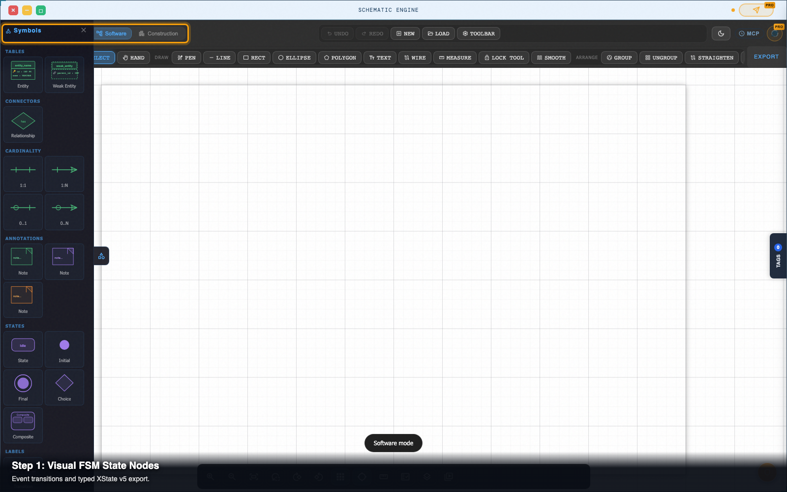
In Schema Editor, open the top mode selector and choose FSM Mode (or load /tools/schema-editor/software/).
The left toolbar populates with state machine primitives: Initial State Marker, State Node, Parallel State Box, Choice Diamond, Final State Marker, and Transition Arrow.
Step 2 — Place initial, state, and final nodes
- Initial Entry Point: Click the solid circle icon and drop it on the canvas.
- State Nodes: Click Add State (or press
S) to place rounded state boxes. Double-click each box to name them:idle,submitting,success, anderror. - Final State: Click the double-circle icon and drop it beside
successto mark the terminal execution state.
Step 3 — Draw event transitions between states
Select the Transition Tool in the left toolbar (or press T):
- Drag from the Initial Marker to
idle. - Drag from
idletosubmitting. Double-click the transition arrow and label itSUBMIT. - Drag from
submittingtosuccesswith labelRESOLVE. - Drag from
submittingtoerrorwith labelREJECT. - Drag from
errorback tosubmittingwith labelRETRY.
Step 4 — Attach guard conditions and action triggers
Select the submitting -> success transition arrow to open the Transition Inspector on the right:
- Guards: Add condition rules like
isValidPayment. - Actions: Add entry or exit action names such as
logSuccessAnalyticsorresetFormContext. - Target: Inspect source and target state bindings to ensure no transitions point to non-existent nodes.
Step 5 — Simulate transitions on the canvas
Click Simulate Mode in the top action bar (or press Space):
- The
idlestate lights up with a glowing active ring. - Click the
SUBMITtransition trigger. - The active indicator transitions to
submitting. - Click
RESOLVEto see the machine reachsuccessand trigger the final state.
Step 6 — Export typed XState v5 TypeScript code
Click Export in the top-right header and select XState v5 TypeScript (.ts).
Schema Editor compiles your visual diagram into clean, typed TypeScript:
import { setup } from 'xstate';
export const checkoutMachine = setup({   types: {     events: {} as       | { type: 'SUBMIT'; payload: { amount: number } }       | { type: 'RESOLVE' }       | { type: 'REJECT'; error: string }       | { type: 'RETRY' }   },   guards: {     isValidPayment: ({ context, event }) => true   } }).createMachine({   id: 'checkout',   initial: 'idle',   states: {     idle: {       on: { SUBMIT: 'submitting' }     },     submitting: {       on: {         RESOLVE: 'success',         REJECT: 'error'       }     },     success: {       type: 'final'     },     error: {       on: { RETRY: 'submitting' }     }   } });
You can also export to JSON State Graph or copy standard Mermaid State Diagram syntax for GitHub docs.
Pro tip: generating state test matrices
Click Export > Test Matrix to Table Formatter.
Schema Editor calculates all valid state-to-event permutations and opens Table Formatter over local IPC with a pre-populated test matrix table, ready for QA test planning.
Next steps
Schema Editor — Draw and edit wiring diagrams, schematics, ERDs, and state machines as real SVG.